?>
Transporting Hard-to-handle Materials With A Horizontal-motion Conveyor
Jay Sullivan
Triple/S Dynamics
Finding equipment that can smoothly and efficiently move a fragile, easily agglomerated, dusty, or light-density dry bulk material, a material with interlocking shapes, or a blend of materials with widely varying bulk densities can present an enormous challenge in a dry processing plant. This article introduces you to one machine that can answer that challenge – the horizontal-motion conveyor, which gently impels material without segregating, aerating or stratifying the particles.
A horizontal-motion conveyor (also called a horizontal differential motion conveyor, differential-motion conveyor or differential conveyor) can convey any free-flowing dry bulk material. But it’s the conveyor’s unique way of applying motion to a solid that provides several benefits for transporting many hard-to handle dry materials.
Like a conventional vibrating conveyor, the horizontal-motion conveyor is a rigid conduit that moves material by applying periodic motion to it. But that’s where the comparison ends: The vibrating conveyor uses impact to propel the material along the conveyor. The horizontal-motion conveyor uses the material’s mass, or inertia, to impel the material along the conveyor. This enables the horizontal- motion machine to gently move many hard-to-handle materials while protecting them from degradation, agglomeration, dusting, buildup, segregation, and other handling hazards.
How the conveyor works
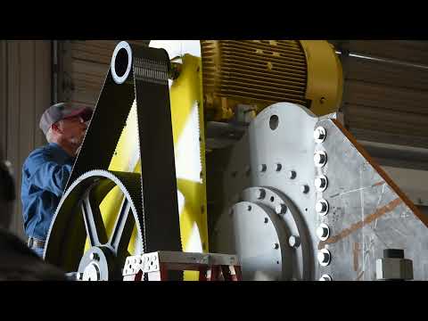
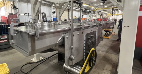
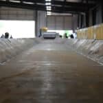
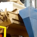
Components. A typical horizontal-motion conveyor, as shown in Figure 1, includes a conveying section, suspension suspension rods or floor-mounted pedestals, and a drive unit. The arrangement of these components can vary to match the application.
The conveying section can be a fabricated trough or enclosed tube (typically from 6 to 48 inches in width or diameter). The suspension rods suspend, or floor-mounted pedestals support, the conveying section; both are shown in Figure 1 for illustrative purposes, but only rods or pedestals are used in one application. One (or more) feed inlet can be located anywhere along the conveying section’s length; each is typically sealed with a flexible boot to control dust (not shown in the figure). One (or more) discharge outlet can be located at any of various points along the conveying section’s bottom to distribute the material.
Each outlet can be fitted with a mechanical discharge gate to start and stop material discharge. The gate, typically pneumatically actuated, can be a slide gate, butterfly valve, or drop gate. For greater control of the material discharge rate, a proportioning gate that provides a range of opening positions from 0 to 100 percent can be located at the discharge outlet. To provide surge accumulation or prevent overfeeding material to a packaging line or downstream process, the conveyor can be equipped with a material dam located just prior to the discharge outlet. The dam drops down across the material bed to prevent material from exiting the discharge outlet while the conveyor continues to operate.
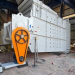
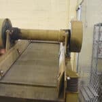
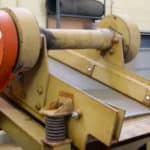
Like the feed inlet and discharge outlet, the drive unit can be positioned at any of various points along the conveyor’s length, depending on available plant space or other requirements. The drive unit has a motor and, typically, four shafts, which are rotated with unbalanced weights in a relationship timed to produce a differential motion. A drive adapter links the drive unit to the conveying section.
Operation. In operation, material is fed through the feed inlet (or inlets) to the conveying section. Via the drive adapter, the drive unit imparts a complex differential oscillating motion to the conveying section – a slow advance stroke that moves the material forward, followed by a quick return stroke that slides the conveying section out from under the material – much like pulling a tablecloth out from under a place setting. This motion gently impels the material forward using the material’s mass, or inertia. The drive unit repeats this cycle several hundred times per minute, resulting in material conveying speeds of up to 45 fpm, depending on the conveyor’s design and the material’s characteristics. As its name implies, the horizontal motion conveyor transfers the material only horizontally or at up to a 2-degree incline.
All of the material is discharged from the first discharge outlet along the conveying section unless the conveyor is designed to split the material flow. In this case the discharge gates operate so that some material exits from one discharge outlet and some passes to exit from a downstream outlet (or outlets).
When used with a standard AC inverter, the drive unit can provide variable speeds. The conveying direction can be reversed by reversing the drive motor’s voltage polarity through the motor’s starter.
How the conveyor handles difficult materials and requirements
The horizontal-motion conveyor’s impelling action can move a very fragile material without damaging it. Common applications are fragile foods such as snack chips, ready-to-eat breakfast cereals, pasta, baked goods, and confectionery products. The conveyor can move these fragile materials from the point of manufacture to final packaging without degrading them.
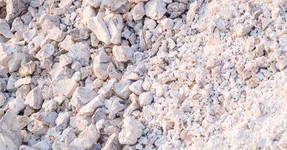
The material’s inertia also prevents the material from impacting the conveying section’s surface. This prevents damage to the particles that could cause them to adhere to the surface and create material buildup. The continuous sliding action of materials on the conveying section’s surface also typically scours the surface clean. Combined with the conveyor’s gentle handling, these operating characteristics allow the conveyor to move hard-to-handle materials such as carbon black and agglomerates such as detergents and some chemicals.
The horizontal-motion conveyor’s use of inertia combined with the conveyor’s resistance to bogging down (that is, damping of the conveyor’s motion, as can happen with a conventional vibrating conveyor’s spring-mass system and vertical motion) under almost any loading condition also allows the conveyor to reliably transfer materials with interlocking shapes, such as fiberglass strands, scrap steel, and metal turnings, as well as light-density materials. These handling characteristics also enable the conveyor to move slurries, such as an ash slurry discharged through an incinerator’s water seal.
The conveyor’s horizontal motion also prevents a dry bulk material from segregating, stratifying, or aerating as it travels along the conveying section. This is because the conveyor doesn’t apply a vertical pitching motion to the material, thus preventing any voids from opening up in the material bed that could allow particles to migrate through the bed. As a result, the conveyor prevents a blend of materials with dissimilar bulk densities from segregating, materials with different particle sizes from stratifying, and fine materials from aerating and dusting during conveying.
The conveyor can also adapt to difficult conveying requirements by operating at variable speeds and reversing direction. For instance, variable-speed operation is important when the conveyor’s speed must adapt to the varying flowrate demands of a downstream process. Reversing direction is useful in other applications, such as when material is fed to the conveyor’s midsection to be conveyed to a destination at one end of the conveyor and, when the conveying direction is reversed, to a destination at the conveyor’s opposite end.
How the conveyor can simplify installation and reduce maintenance and space requirements
The horizontal-motion conveyor can be as long as about 200 feet and can handle up to hundreds of tons of material per hour using a single drive unit with a single motor. This inherent simplicity makes the conveyor easy to install and maintain.
Unlike a conventional vibrating conveyor driven by a spring-mass system, the horizontal-motion conveyor is inertially driven, typically with rotating unbalanced weights. This means the conveyor has no springs that need to be maintained and “tuned” to produce a certain conveying speed. The conveyor also doesn’t require as much space as a vibrating conveyor, whose spring-mass system uses bulky counterweights and spring suspensions.
The lack of springs and other heat-sensitive components in the conveying section makes the horizontal-motion conveyor suitable for moving hot materials with temperatures over 1,000’F and for installation in hot environments, such as in a furnace-charging application where the conveyor’s discharge end must be installed inside the furnace.
The trough or tube conveying section contains no moving parts, so the material contacts only the surface on which it slides, thereby reducing cleaning and maintenance requirements.
The conveyor has few, if any, mechanical components to maintain. A horizontal-motion conveyor on floor mounted pedestals has no mechanical components along the conveyor’s length. When the conveyor is suspended from the ceiling or a support beam, the only mechanical components are suspension rods.
Some selection criteria
Carefully consider your material characteristics and process requirements when selecting a horizontal-motion conveyor. This will help you choose features that will deliver the conveying performance you need.
Conveying section. If you must isolate your material from your plant environment – whether to control dust, provide pressure isolation, blanket the material with an inert gas, or provide other environmental control – you can select a tube conveying section.
Whether you choose a trough or tube conveying section, make sure the section’s construction matches your application requirements.
To protect your material from cross-contamination in a trough conveying section, you can add an integral cover to the trough that can be removed for conveyor cleaning and maintenance. Or you can mount a cover above the trough so that a gap remains between the trough and cover to allow workers to access the conveyor. You can also install chutes at each discharge outlet (Figure 1) to minimize cross-contamination.
If the material stream feeding your trough conveying section will be wide, such as the discharge from a granulator, you can consider using a trough with angled rather than vertical sides.
Whether you choose a trough or tube conveying section, make sure the section’s construction material matches your application requirements. A carbon steel conveying section will handle many materials, but if you’ll convey a food or other sanitary material, you can choose stainless steel construction. If your material is sticky, such as dishwashing detergent, select a conveying section made of ultrahigh- molecular-weight polyethylene (UHMW-PE), which prevents sticky particles from adhering to the surface. To convey a corrosive material, such as chlorinated bleach powder, you can choose a titanium conveying section. For an extremely high-temperature application, you can select a Hastelloy conveying section.
Discharge components. To provide on-off discharge control, choose a slide gate, butterfly valve, or drop gate for each discharge outlet. Which type is best depends on your material’s characteristics. For more flow control, choose a proportioning gate or a combination of proportioning and discharge gates. To provide surge accumulation, consider installing a material dam at each discharge outlet.
To convey your material to more than one destination – such as to different packaging machines that each fill different-sized packages – you can split the material flow by using multiple discharge gates along the conveyor. You can use a proportioning gate to match any discharge gate’s flowrate to a specific packaging machine’s demand flowrate.
Conveyor configuration. Choosing the drive unit’s location along the conveyor’s length typically depends on your plant’s space limitations. Other factors are the feed inlet and discharge outlet locations on the conveyor.
If you need to convey your material over a distance longer than 200 feet or want to convey the material to multiple widely separated locations, you can install one or more additional horizontal-motion conveyors . This requires intersecting the discharge outlet of one conveyor with a feed inlet on the next conveyor. Each conveyor can be installed at an angle to the upstream conveyor to accommodate your plant’s space restrictions.
If you need to simultaneously convey several different materials to different destinations and have limited floor space, you can use a multiple-channel conveyor. This conveyor consists of up to four attached, parallel trough or tube conveying sections and is powered by a single drive unit and motor.
Where to go from here
Contact a horizontal-motion conveyor supplier for more information about how to select a conveyor for your application. The supplier can help you determine which conveyor features you need by comparing your material characteristics with those of other materials the conveyor has handled or by running samples of your material in a horizontal- motion conveyor test unit. The supplier will also determine the optimal width or diameter for your trough or tube conveying section and the correct size for your drive unit and motor.
Whether you’re looking for a more reliable way to convey your hard-to-handle material or just trying to reduce mechanical conveyor maintenance, working closely with the supplier can help you choose the right features and components to deliver conveying success.