?>


The Vibrating Conveyor For Incinerator Ash For Handling Systems
This paper describes the application of vibrating conveyors to the handling of ash from mass-burn incinerators. The characteristics of two different kinds of conveyor, the natural frequency vibrating conveyor and the differential velocity, or “horizontal differential” conveyor, are compared. Factors to consider in selecting and specifying a conveyor design are discussed, in relation to performance, maintenance and abrasive wear.
NOMENCLATURE
Fi = inertia force
f = frequency of impressed force
fn = natural frequency of a spring-mass system
k = spring rate, in terms of force per unit of displacement
m = mass of the vibrating body
Wr = unbalanced weight of a rotor times the distance to its centroid from the axis of rotation
x = displacement (one-half of total stroke)
Φ = phase angle between impressed force and system displacement
WHY VIBRATING CONVEYORS?
Bottom ash from mass-bum incinerators includes grate siftings, and may also include fly ash and scrubber residues. If the incinerator employs a water-sealed extractor, the emerging ash will be wet, and at slightly elevated temperatures ranging from 120-180°F (50-80°C). It may be extracted from the incinerator discharge with a ram extractor, or a submerged drag conveyor. In some applications it may desirable to avoid wetting the ash, while still maintaining an air seal. In such cases, the ash may exit the incinerator at elevated temperatures, up to as much as 1800°F (985°C), although in some systems the ash may exit dry at lower temperatures.
Because of the heterogeneous nature of the bottom ash, drag conveyors can be maintenance headaches. Belt conveyors can be used for transporting the ash, after extraction by water-sealed ram or submerged drag, but the vibrating conveyor is commonly preferred, for the following reasons:
(a) The steel trough better withstands abuse from impact loading by large, heavy, irregular, and sometimes sharp-edged objects typical of those found in mass-bum bottom ash, that may drop from the extractor through a height of several feet.
(b) The cross section of the trough can be made deep enough to contain, without splash or spillage, the unit volumes discharged from a ram extractor at each cycle, even when downstream extractors in multiple. boiler systems discharge onto a mass arriving from other extractors upstream.
(c) Housekeeping problems due to water runoff, spillage and scraper droppings, common to belt conveyors, are avoided.
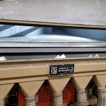
(d) The trough can, if necessary , be enclosed to seal against pressure differentials. Although this is not a common requirement, several installations of John Zink rotary kilns are equipped with Triple/S Dynamics air-sealed dry ash dischargers.
(e) The steel trough can handle dry ash, or grate siftings, at elevated temperatures that would damage a rubber belt, or drag conveyor, as it can be surface cooled and exposes no moving parts, other than the vibrating pan surface, to contact with the hot and abrasive material.
MODES OF VIBRATION
There are two modes of vibration that can move materials ranging in form from bulky, somewhat amorphous or plastic wet pulps (water-quenched ash), dry granular materials, or solid objects (unit loads ). One utilizes a simple harmonic vibration, pitched at an upward angle to the plane of the conveying surface, and the other, a complex, differential velocity straight-line oscillation in the plane of the conveying surface.
For the purpose of differentiation, in this paper the harmonic-motion conveyor will be called the “vibrating” conveyor, and the differential velocity, the “horizontal differential “.
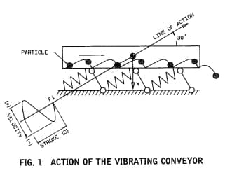
For the simple harmonic motion to cause a mass or object to move in one direction, its line of action is pitched upward from the conveying surface, to impart a trajectory effect. The mass, or object, moves along the surface in a series of short trajectories, as shown in Fig. 1. Optimum operating conditions, in terms of amplitude, frequency and pitching angle, have been developed for water-quenched ash through trial and error, and will be described later in this paper.
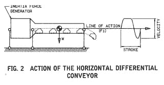
The differential velocity motion, having different mean velocities and peak accelerations through each half of a cycle, through differential friction can cause movement of the mass or object in the direction of the lower mean velocity. The line of action may be parallel to the conveying surface; the mass, or object, will slide along the surface in a series of “slip-suck” sequences. as shown in Fig. 2.
All the differences in design and performance between the vibrating conveyor and the horizontal differential conveyor stem from the differences in the kind of motion required to cause the mass, or object, to move in one direction. The most significant difference between the two is the presence, or absence, of motion in the plane normal to the plane of the conveying surface.
HARMONIC VIBRATION
Steady-state, as opposed to transient, harmonic vibration can be generated by applying a periodic force to a spring-mass system. If the frequency of the impressed force is at, or near, the natural frequency of the spring-mass system, the vibration can be maintained with a very small input force. This is the principle employed in the design of the natural-frequency vibrating conveyor.
The spring-mass system in the vibrating conveyor, in its simplest form, comprises the conveyor trough and associated “live” structure, springs made of some elastic material such as steel, rubber, or fiber-reinforced plastic laminates, a means for applying a small periodic impressed force, and a fixed base against which the spring force reacts. This system is shown schematically in Fig. I.
The impressed force may be applied by a fixed-displacement eccentric crank, usually but not necessarily connected to the trough structure through a resilient coupling, or by a rotating unbalance or linear inertia force that applies a constant periodic force component along the line of action at the desired frequency.
The spring-mass system has a natural frequency expressed by the relationship
fn= (k/m)1/2
If the frequency of the impressed periodic force is equal to this natural frequency , the resulting vibration is said to be “resonant,” at frequency ratio if(f/fn) = 1. At this condition, the inertia force developed by the vibrating mass is exactly equal to the spring force applied:
Fi = m · f2 · x = kx
The displacement x appears on both sides of the equation, and therefore drops out, meaning that, at the condition of resonance, amplitude may increase without limit, up to the elastic limit of the springs or the limits imposed by damping or mechanical restraint, whichever occurs first.
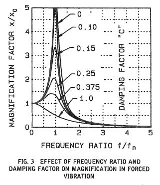
The ratio of the displacement developed in a steady state, forced harmonic vibration, to the static displacement that would result from the static application of the impressed force to the spring-mass system, is called the “magnification ratio”, X/Xαn. It can be seen, in Fig. 3, that this ratio depend s upon two variables, the frequency ratio f/fn and the damping factor C.
The natural frequency of the vibrating conveyor of a given spring rate is determined by its empty “live weight” plus from one-third to one-half the weight from the material loading in the trough; this latter can be, and usually in practice is, a variable.
The damping factor is determined by th e internal damping in the system, plus the damping properties of the material being conveyed. Internal damping is a function of the hysteresis losses in springs, stabilizer bushings if used, elasticity in the exciter (impressed force) drive system, and the overall rigidity of the live structure. Material damping is governed by the nature of the load being conveyed; wet, amorphous or plastic pulps seem to apply more damping than inelastic solids in unit or bulk dry granular form . The damping effect results from friction losses associated with the work expended in lifting the load during each cycle, slippage of the load on the conveying surface, and, in the case of dry granular materials, interparticle friction.
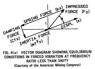
The interaction of the impressed force, inertia force, spring force, and damping force is illustrated in the vector diagrams of Fig. 4. For the vibrating system to be in equilibrium at any frequency ratio, the vector sum must be zero on any axis.
The diagram in Fig. 4(a) represents the equilibrium condition at frequency ratios less than unity. Because the spring force is greater than the inertia force, the excess must be opposed by the impressed force, which also must oppose the damping force, with a component at right angles to the inertia force.
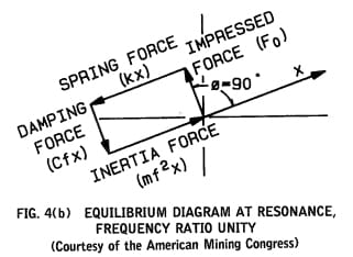
In Fig. 4(b), the frequency of the impressed force has increased to match the natural frequency of the spring-mass system. The spring force now equals the inertia force, and the impressed force has only to oppose the damping force.

In Fig. 4(c) , the frequency of the impressed force has increased beyond resonance. Now the inertia force exceeds the spring force, and the difference must be supplied by the impressed force . This is the condition that exists in the springless (sometimes called “brute force “) system, where the spring force along the line of action is negligible, and the impressed force equals the inertia force, leading it by 180 deg. at zero damping.
From the foregoing illustrations, it will be seen that very little power will be required, in the natural-frequency condition represented by Fig. 4(b), to apply the impressed force needed to maintain the steady-state oscillation, if the frequency ratio remains near unity and damping is light and constant. In practice, the frequency ratio is set at a value slightly below unity, to provide some marginal stability against the effects of increasing loading.
It is evident that changes in frequency ratio caused by variances in material loading, plus any variance in the damping factor, will affect magnification, and consequently amplitude, unless :
( a) the frequency of the impressed force is adjusted to maintain a constant ratio, or
( b) the magnitude of the impressed force is adjusted to compensate for the change in magnification.
Automatic frequency compensation is theoretically possible, but neither practical nor desirable; it would lead in the usual case of increasing frequency ratio, to progressive reductions in forcing frequency with accompanying reductions in conveying rate, compounding to a full stall as the frequency ratio moves above resonance.
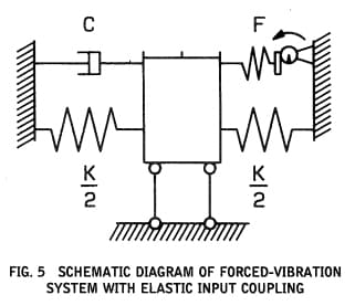
The most practical way to maintain amplitude stability at constant frequency, over a limited range of variance in frequency ratio and damping factor, is with the fixed-displacement crank, or eccentric, acting through an elastic coupling of significant stiffness, as shown schematically in Fig. 5. This arrangement makes use of the change in phase angle, Φ, (Fig. 4) caused by changes in frequency ratio, to provide automatic compensation through the resulting changes in physical displacement of the coupling. The range of stability is limited by the stiffness, or spring rate, of the coupling.
If a fixed-value impressed force is applied, by means of a rotating unbalance or linear inertia-force generator, the equivalent coupling stiffness is zero; the impressed force at constant speed will be constant at any frequency ratio, and the range of stability will be very narrow. This characteristic limits the constant-force exciter drive to applications where damping is light, and material loading fairly constant.
On the other hand, if the impressed force is applied through a solid coupling, such as a wrist pin, the equivalent coupling stiffness is infinite, and the range of stability will extend to the strength limit of the driving elements and structural connections. Because of its susceptibility to overloading, this solid drive arrangement, once common, has given way to the elastically coupled exciter drive.
Spring force reactions applied to the base may be absorbed in a massive foundation, or in 8 heavy reaction frame mounted on springs of low stiffness, or cancelled with a mirror-image dynamic counterweight system.
HORIZONTAL DIFFERENTIAL MOTION
The nonharmonic motion cycle required by the horizontal differential conveyor cannot be developed in a simple tuned spring-mass system . The differential force function can be generated by a mechanical linkage, or by a system of rotating unbalances.
The mechanical linkage is not suitable for large, heavy conveyor applications, as the reaction cannot be counterbalanced successfully. The system of rotating unbalances, however, can be integrated with the vibrating structure, to generate an internal straight-line inertia force that causes the system to oscillate along a single horizontal axis. Forces normal to the desired line of action are canceled by the 180 deg. angular opposition of pairs of centra-rotating unbalances .
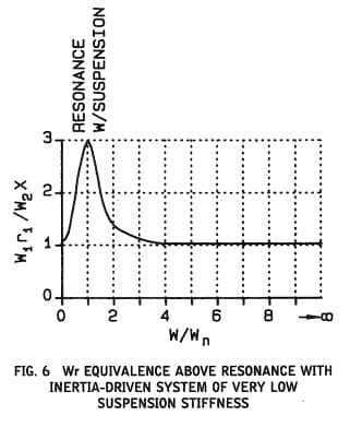
This system is always in equilibrium, its center of mass remaining stationary. If its suspension is springless and frictionless the action and reaction forces cancel out. with no transmission on the line of action through the suspension to supporting structures. Its natural frequency is close to zero (it is not truly a free body, as it must be suspended from some fixed reference, so its natural frequency can only approach zero), so that the frequency ratio approaches infinity. The net Wr, on the resultant axis, of the rotating unbalance system equals the Wx of the vibrating body containing the unbalances; there is no magnification. and amplitude is, therefore, constant at all frequencies in its operating range, as shown in Fig. 6.
Amplitude is also unaffected by the amount of, or variances in, material loading, because the motion, confined to the plane of the conveying surface, doesn’t lift the load. Neither is amplitude affected by material damping characteristics.
Amplitude is affected by any attached masses, such as material deposits, that may be added to the bare weight, but only in direct proportion to the weight increment.
ADAPTATION OF VIBRATING AND HORIZONTAL DIFFERENTIAL CONVEYORS TO ASH FROM MASS-BURN INCENERATORS
The special problems associated with the handling of incinerator residues in a vibrating or horizontal differential conveyor include:
(a) Uneven material loading lengthwise of the conveyor pan, due to the intermittent discharge from the extractor. This can be compounded, in multiple-boiler installations, by ” piggy-backing” of the discharges from one or more downstream extractors on top of masses discharged from upstream extractors .
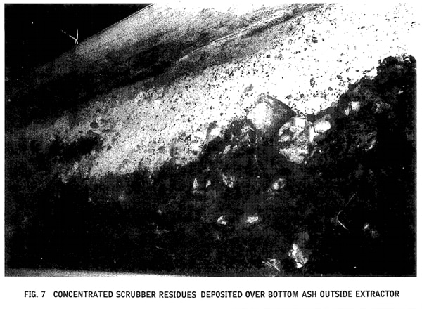
(b) Finely divided materials, including economizer, ESP or baghouse fly ash, and scrubber residues, if moistened by contact with wet bottom ash, may form attached deposits that can build up to large masses. Scrubber residues are worse than fly ash alone. Figure 7 shows dry scrubber residues deposited on the bottom ash mass outside the extractor, and Fig. 8 shows the resulting deposit accretion.
(c) The fine fraction of the bottom ash includes highly abrasive materials such as sand, glass, and other vitrified fines, which segregate under vibration to the bottom of the material mass, and promote relatively rapid wear of metallic conveying surfaces.
(d ) Ash discharged from water-sealed extractors contains varying amounts of entrained free water.
THE VIBRATION CONVEYOR
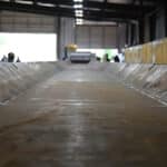
A correctly applied vibrating conveyor does not accumulate deposits if scrubber residues are not present. Travel rate is highly sensitive to mass and moisture content, and has been observed to vary, in the same unit, between 7 and 20 fpm (36- 100 mm/s ), with a “normal” rate of 12 fpm (61 mm/s). Its tossing action stratifies fines quickly and squeezes out moisture, creating puddles of wet slurries that move little until they are pushed on by an overtaking mass.
If moisture conditions are right for the accretion of deposits, particularly if dry scrubber residues are present, deposits will build quite rapidly in the vibrating conveyor, requiring frequent removal to prevent the conveyor from stalling due to excessive upward shift in frequency ratio.

Experience in the industry has established operating parameters for vibrating conveyors that insure best performance in the ash handling application. They are:
(a) A dynamically balanced design, with full mirror- image counterbalance, is essential because of the size and weight of the typical conveyor, and the need for maximum stability under typical operating load conditions.
(b) Optimum travel rate, to maintain the material load in the conveyor trough within safe limits for stability, is achieved at an amplitude or about I in. (2 5.4 mm) total stroke and rpm set for a 2 “g ” peak acceleration at 375 cpm (6 .25 cps), at a pitching angle of about 30 deg. This limits the impact effect of the vibration, by holding the vertical force component to plus or minus 1 ” g” (2 g sin 30 deg.).
(c) The exciter drive must provide maximum stability under varying conditions of loading and damping, through use of eccentric cranks working through elastic couplings whose stiffness should be not less than 10% of the total spring force at maximum (Φ = 180 deg.) displacement. Constant-force excitation, as from a rotating unbalance, under the typical operating conditions is highly vulnerable to detuning to a full stall.
(d ) Performance is improved by slightly declining the conveyor from feed end to discharge; this helps both to drain free water and to accelerate travel rates.
THE HORIZONTAL DIFFERENTIAL CONVEYOR
The horizontal differential conveyor operates by sliding the material mass over the conveying surface through differential friction generated by its quick return motion in the plane of the surface. This gives the design certain performance advantages over the vibrating conveyor, which include:
(a) The inertially-driven system is self-balancing in the plane of its motion , which eliminates the need for counterbalancing. The single-point inertia force application is feasible, because the structure is equivalent to an end-loaded column.
(b) At a total stroke of 1 in. (25.4 mm) and frequency 280 cpm (4.7 cps), travel rate is fairly constant, at 18-20 fpm (91-102 mm/s), and is little affected by variances in mass or moisture content.
(c) Stratification of fines is reduced. Heavier objects act as scrapers, helping to control deposit accretions when moisture conditions favor their development.
(d) The system is tolerant of deposit accretions if they do develop. Amplitude does not depend on magnification at resonance, and will be reduced only in proportion to the weight added by the deposit buildups.
(e) Performance is not significantly improved by declining the trough downward from dead level.
THE MECHANISM OF ABRASIVE WEAR
The principle cause of wear in vibrating or horizontal differential conveyors handling bottom ash is abrasion from pulverized glass, sand, and vitrified fines scrubbed over the conveying surface under the weight of the material mass, or heavy objects.
The stratification of fines caused by vibration accelerates wear by concentrating them at the interface between the mass being conveyed and the conveying surface. The wear rate increases in some proportion to the weight of the unit mass moving along the surface. If the mass is, as is usually the case, distributed unevenly across the width of the surface, the transverse wear profile will follow the weight distribution.
Abrasive wear requires both pressure and relative movement between the abrasive medium and the wearing surface. This condition is fulfilled in both vibrating and horizontal differential conveyors. Wear is accelerated by the presence of free water at the interface, due in part to increased slippage. Either one would be 100% efficient as a conveyor if the material load displacement were the same as the conveyor’s in the forward direction (zero slip), and zero in the return direction (100% slip) . “Slip” would thus be defined as the forward displacement per cycle of the material divided by the sum of the forward and return travel of the conveyor, or 50% at 100% efficiency. Then, if it is assumed that the material load does not travel backward with the return stroke of the conveyor, as if it were stuck to the surface, the percent slip calculated in this way should be a measure of relative movement between load and surface.
Comparing the vibrating conveyor with the horizontal differential for percent slip, the vibrating conveyor observed, with a normal travel rate of 12 fpm (61 mm/s) at 1-1/16 in. (27 mm) amplitude at 30 deg. pitch and 350 cpm (5.8 cps), exhibited a slip of:
Percent Slip = 100 X [(1 – [144/(350 X 1.0625 cos 30 deg. X 2)]] = 77.6%
For the horizontal differential conveyor, at total stroke of 1 in. (25.4 mm), and frequency 280 cpm (4.7 cps), having an observed travel rate of 18 fpm (91 mm/s),
Percent Slip = 100 X {1 – [216/(280 X I X 2)]} = 61.4%
Corresponding transport efficiencies would be, for the vibrating conveyor, 44.7%, and for the horizontal differential, 77.1%.
From the foregoing observations, it might be assumed that wear rates would be appreciably less for the horizontal differential than for the vibrating conveyor. Studies conducted by the authors at four different locations, however, do not as yet offer convincing support for this hypothesis.
These studies, still underway, have included periodic measurements of the thickness of conveying surfaces at four different incinerator sites, two of them having vibrating conveyors and two with horizontal differential conveyors. All four have troughs constructed of 400 BHN heat-treated steel plate, 3/8 in. (9.5 mm) thick. One of the vibrating conveyors serves three boilers rated at 375 TPD (341 tpd) each, the other two at 250 TPD (227 tpd). One of the horizontal differential conveyors serves two boilers rated at 100 TPD (91 tpd) each, and the other, two at 250 TPD (227 tpd). Measurements are made with a Nortec UT ultrasonic thickness tester, at transverse sections spaced at 12 in. (305 mm) intervals and longitudinal spacings of 5-20 ft. (1.5-6.1 m), the longitudinal spacing governed by accessibility. The differences between wear measurements at intervals of 6 months to 1 year are recorded as the adjusted thickness loss per year of service.
The scatter of data in each of the four cases under study masks any possible significant differences in the wear rates experienced by the two kinds of conveyor. It cannot, therefore, on the basis of this data, be said that either kind is better or worse than the other. Some tentative conclusions about wear ~ be reached, however.
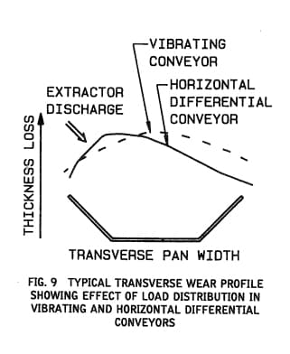
(a) The wear profile at any transverse section reflects the distribution of the material load across the section. If the load were more uniformly distributed, as it could be from a beveled discharge face, the rate of maximum wear could be reduced by as much as one-third to one-half the values recorded, as shown in Fig. 9.
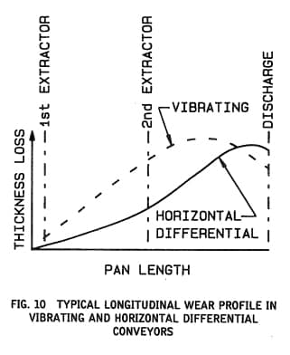
(b) There is evidence that the vibrating conveyor creates, by its action, a better material spread across the surface than the horizontal differential, producing a more uniform transverse wear pattern downstream from the extractors. By the same token, the more rapid stratification causes a faster rise in rate of wear just downstream from each extractor . The typical pattern is for wear to increase to a maximum in 40-60 ft. (12-18 m) downstream from the last extractor, then to decline slightly from there to the discharge. A typical longitudinal wear profile is shown in Fig. 10.
(c) In the horizontal differential conveyor, wear increases more gradually, and continues to rise to a maximum at the discharge (Fig. 9).
(d) There is evidence that, if distribution of material across the width of the pan were improved from that in the cases under study, maximum wear rates would be significantly lower for the horizontal differential than for the vibrating conveyor.
(e) If it is assumed that wear rates are in direct proportion to material throughput, ignoring the effects of unequal transverse load distribution, among the four cases under study the single-point measurement of highest wear yields a specific wear rate of about ( 1.6-1.9 X 10⁻⁶ in./year)(ton-year/ ft width). In SI units, this becomes (13.7-16.3 X 10⁻³ rom/year) (mton-year/ mm width). The higher rates correspond with the lower tonnages, casting doubt on the assumption that wear is directly proportional to tonnage handled.
If these tentative results are accepted, at face value, the operator of a 500TPD (455 tpd) plant could expect a maximum metal loss of 3/16 in. (4.8 mm) in a localized area of greatest wear, in a 4 ft (1219 mm) wide conveyor, after 26-31 months of service. In a 1200 TPD (1089 tpd) plant, with a conveyor of the same width, the same amount of wear could result from as little as 13 months’ service.
There is evidence that the mill scale on new plate retards the initial wear rate, allowing an extension of 3-6 months to the calculated terms.
Allowable wear in the vibrating conveyor is limited by the onset of flutter induced by the normal component of its motion, resulting in fatigue cracking. In the horizontal differential conveyor, wear can proceed to the minimum thickness required to support the load, or to resist impact at extractor discharges, because there is little or no vibration-induced flutter.
MAINTENANCE REQUIREMENTS FOR VIBRATING AND HORIZONTAL DIFFERENTIAL CONVEYORS IN ASH HANDLING SERVICE
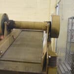
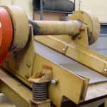
Replacement parts in the natural frequency vibrating conveyor include springs, elastic coupling elements, eccentric bearings, housings and seals, toggle or stabilizer arms, rubber bushings if used, and trough or liner plates.
THE VIBRATING CONVEYOR FOR INCINERATOR ASH HANDLING SYSTEMS
Springs are life-limited by their working stress range, quality of manufacture , and metallurgy. Buyers of vibrating conveyors should know the design stress range, alloy composition, and the manufacturing process employed, in order to evaluate life expectancy.
Nonmetallic composite flat springs or stabilizers should not be employed in ash handling service, because of their susceptibility to abrasive wear at end clamps, and usually limited column stability under heavy loading.
Bearing life expectancy is not significant, as in normal operation loads are light and indeterminate.
Replacement parts in horizontal differential conveyors currently available include rotor shafts, bearings, bearing housings, grease and oil seals , coupling gears, suspension rockers and seats, and trough or liner plates. All these parts, except suspension parts, and the trough or liner plates, are contained in a unitized drive module. A spare module may be kept on hand for quick replacement and subsequent repair in the shop or at the factory.
Bearing life can be predicted, within the broad limits of the AFBMA formula for B10 life, because centrifugal forces apply a known radial load, fixed with respect to the inner race. The application factor used in this formula should be set at 1.25, and the multiplier of 5 X B10 life may be applied when using SKF “Super” bearings. Bearing life in this kind of drive can, therefore, be a meaningful factor for evaluation, if it is kept in mind that installation factors may overshadow the empirical calculation.
COPING WITH CONVEYOR PAN WEAR
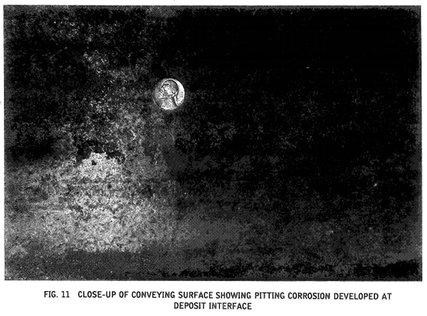
It has already been seen that wear of the conveying surface, in either kind of conveyor, is a significant problem in maintenance. If deposits are allowed to accumulate, corrosion under the interface can be severe, as shown in Fig. 11. Wear surfaces should be hardened to 400 BHN (nominal). Construction in either kind of conveyor should provide for easy replacement, in 10 or 20 ft. (3-6 m) sections, without affecting “live frames”, using only bolts and seal welding at abutting ends.
Use of replaceable liners is not well-advised, as they add weight which compounds initial cost, and their replacement offers little or no time advantage over the replacement of pan sections of equal thickness. For the same reason, heavy impact plates at the extractor discharges are not worth their cost, provided that adequate support is provided underneath the bottom plate to limit deformation from the occasional heavy impact. Abrasive wear at the extractor discharges is less than it is downstream from the last one in a series.
Wear life will be enhanced, even doubled, in either kind of conveyor if care is taken in designing the interface between conveyor and extractor, for the reasons explained previously. Spillage and “roll-off”, a legitimate concern for the designer, can be contained with elevated side guards attached to the conveyor, opposite to each discharge face.
The horizontal differential conveyor can tolerate greater weights of deposit accumulation, without de~ grading performance, than can the vibrating conveyor; but in either case, the pan should be kept free of permanent deposits, to prevent corrosion and to avoid accelerated wear caused by channeling of the load around the deposits.
Either kind of conveyor can be considered self-cleaning when handling bottom and fly ash only, if the fly ash is wetted sufficiently at the point of introduction, but if scrubber residues are introduced without the addition of enough water for quick absorption, deposits are likely to form. In this latter case especially, covers, if used, should allow quick access for cleaning, or enough clearance over the pan to allow a man to stand while pushing the scraper.